Month: August 2013

03 PIR motion sensor

Hy guys!

Today I finally finished example code for PIR and decided to do little post about it. PIR is Passive infrared sensor usually used for outdoor lights (I really can’t remember any other usage except as part of the alarm system for your room :P). I wouldn’t like to explain how does it work because this page made perfect job.

Something that’s really important to you as programmers is kind generated signal when PIR senses a motion. First of all this is how it looks like (down here). On the left side is lens and on the right you see green board with sensor. Be careful, when you connect sensor to the Stellaris, you don’t exactly connect sensor to the Stellaris, but you connect one pin from chip that is bellow that green board to the Stellaris.


Well when that is clear, now I can “comment” program I made. The task was to make simple code that will turn on on-board LED when the sensor senses the motion, else LED will be off.

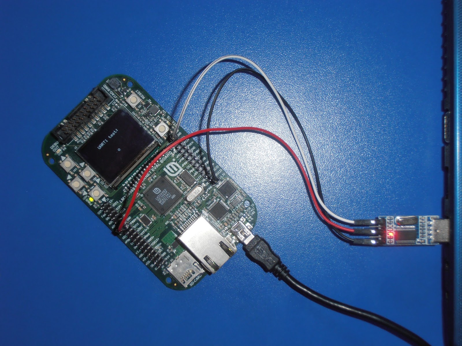
On picture above you can see how was it all connected. Little tip, always connect GND wires. When you use 2 different power supplies also connect GND together! When I was younger it made me a lot of problems (I was inexperienced). Since the PIR sensor has to have its power supply, I decided to bring it from Stellaris board. On green PIR sensor board was written +5V, OUT, GND, so it has to be connected with respect to that marks. Only OUT pin is up to you. I decided to connect mine at PA7 pin at Stellaris board (or written at the board SDA1).

Little explanation why we have to connect power supply for PIR sensor board:

As I have mention earlier, below sensor is chip which is used for decoding signal (that sensor sends to it), every chip needs to have its own power supply so this +5V, GND is for that particular chip. I think I mention everything that could cause problems while trying to make something with PIR sensor. Now it’s time for code explanation…

Full example code you can download HERE.

As you can see on pictures bellow before little guy left LED on Stellaris board is OFF, and when little guy passes by it goes ON.


Everything important for code is explained in comments. You’ll see in there that I made few .c files for PIR and LED, it’s mostly because I didn’t want have troubles with shifting pins in GPIO functions, and I wanted to use my own declarations, not the ones in gpio.h file.

DOWNLOAD CODE

02 UART communication

Hello, here’s second tutorial, also some basic stuff. I’m going to explain how to accomplish communication between computer and lm3s6965. For this task I decided to use serial communication through USB port (COM3-this is something  you can easily find out by using program Terminal Bray, I will explain that later).

For this project you’ll need:

– lm3s6965 (Stellaris board, or some other, the principle is the same)
– computer with USB port
– program Terminal Bray
– 3 female connector wires
– USB-TTL / STC-ISP (about few few dollars on ebay, pictures bellow)

Something about our task. We would like to send one character from our computer to the Stellaris and than display that character on OLED.  Here is block scheme, for better understanding and code writing.

I had a little problem in beginning because I had no idea how to write a code for something like this (this was my first project ever whit communication between computer and a chip). And  TI example code wasn’t a big help. When I remember all that “problems” it makes me laugh, because it’s so simple that I’m almost ashamed of talking “I know how to make successful serial communication between computer and stellaris”.

Now let’s get down to business. On my GoogleDrive you can download whole project ith comments.

LINK

If you haven’t configure your onboard debugger already, here is little tip how to do that (so that you can download program to the stellaris).

Configuration of OnBoard Stellaris Debugger in Keil uVision 4:

Open this window by clicking on Flash-> Configure Flash tools-> settings should look like there on picture.

After that’s completed, Left click on project-> Options for target ‘UARTDisplay’… or F7-> Choose Debug and set properties like on picture down here

Now you have to connect Stellaris and USB-TTL to the laptop. Here is picture how to do that. You have to be careful how you connect 3 of that wires. Black one is 3.3V, red one is Tx (because computer transmits data to stellaris) and white one is GND. You probably ask yourselves “why I have to connect 3.3V and GND?”. Well it’s because when you’re not in debug mode, and your stellaris is not directly connected to the computer it has to have some sort of battery.

After that you can Build (Project-> Build target) your project and start downloading (Flash-> Download) it to your Stellaris. When it’s done, open Terminal Bray (remember that program from the beginning of this post?! On picture bellow is what you have to set:

COM3 is set by Terminal Bray. It depends on where did you put USB-TTL. Speed depends on your code, where you define it, and when it’s ready click connect (on mine picture is disconnect). After all this you can type a letter or a number and it will be shown on you display.

=) Hope it helps!

01 How to manage everything (for nice start) in Keil uVision4

This tutorial is for complete beginners in Keil.

You can download Keil here. Be careful, if you have uController from Texas Instruments (ARM, cortex-M) download file “MDK-ARM”.

1. Find out which uprocessor you have. I have this little powerful boad: Stellaris lm3s6965, so I will make empty project for it =) (processor: lm3s6965)

2. Open Keil and pick Project->New uVision Project -> Select empty folder and choose its name (mine is Example)-> Save-> Find your uController (mine is in group Texas Instruments, lm3s6965)-> OK-> now there is question: “Copy “Startup.s” to Project folder and add file to Project?”, click NO. This is because you’ll have to add one later (which is litter different than this one).

3. Rename Source group in src. Right click on “Source group1” and “Manage components…”. Simply rename “Source group1” into “src”, and click “OK”. Also add another group “library”.

4. Now go to folder where you created folder Example. Folder “drivers and inc” you can download from mine Google drive. I didn’t have enough time to make all includes in drivers workable. So everything you’ll need to to is to delete this kind of parts “driverlib/”, “inc/”, “drivers/”, and leave only .h file (it’ll have to look like this:

#include “gpio.h”

5. Now it’s almost done! Create new file (ctrl+N), and save in src folder (file name: “exampleFile.c”). Also DO NOT FORGET ADD .c EXTENSION! Add that file to the src group in Keil (Right click on Target1-> Manage components-> Add “exampleFile.c”-> OK). “1.” and “2.” means that first you have to add file and then click OK, after that it will be shown in src group. While you’re in Manage components add “startup_rvmdk.S” (this file is MUST HAVE), and for example “gpio.c”, these 3 files you have to add in src group, and “driverlib.lib” file in library group. Then click OK.

6. As I have already mentioned in step 4., open “gpio.h”, and where you see in include files path like driverlib/, or inc/ or something like this, delete it and then try to compile. Since you  probably didn’t write main function, compiler wouldn’t want to compile it.

7. So…Just write something like

int main ( ){
return 0;
}


00 Hello

Hi guys, it’s my first post on this blog. For start I would like to tell you something about me and future posts.   Currently I’m a student at Faculty of electrical engineering and computing in Zagreb, last 3 years I’ve been programming microcontrollers. PIC was mine first one, and now I’m interested in ARM. There hasn’t been much big projects, but there has been some smaller ones. Some of them I would like to share on this blog.

Some ideas are:

– how to make completely new blinky project in Keil uVision 4 (I had quite big problems with making project from scratch, mostly because I’m a only beginner with ARM microcontrollers) – how to send character from computer to lm3s6965 by serial port
– well that’s it for now =)  

Enjoj!  
P.S. There’s another blog for those who like geek fashion Geeke Fatal